As construction machinery and other mobile equipment increasingly move towards electrohydraulic control, CAN communication is becoming an important part of joystick integration. But choosing a CAN joystick is not simply a matter of selecting a CAN output. OEMs also need to determine which protocol fits their machine architecture: CANopen or SAE J1939.
Both protocols are widely used in mobile machinery, but they serve different purposes and are not directly compatible. J1939 is strongly established in powertrain and vehicle networks, while CANopen is commonly used for working functions such as hydraulic valves, joysticks, I/O modules and sensors.
In this article, we look at the differences between CANopen and J1939, where each protocol is typically used and what OEM engineers should consider when specifying a joystick.
CAN is the road, the protocol is the language
CAN (ISO 11898) defines the physical layer and the data link layer: two wires, differential signalling, message priority through the identifier and robust error detection. It does not define what the eight data bytes of a message mean. A higher-layer protocol adds that meaning: which message carries the joystick position, how a device gets its address, how faults are reported and how a device is configured.
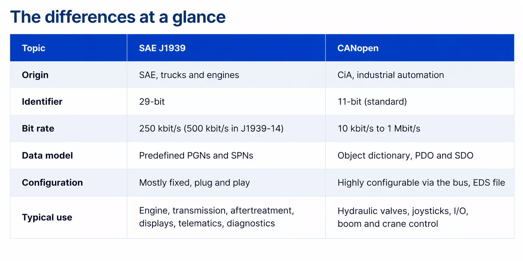
SAE J1939 and CANopen both run on classical CAN, but they are not compatible. J1939 uses 29-bit identifiers, CANopen normally uses 11-bit identifiers, and the two organise their data in completely different ways. A J1939 joystick will not work on a CANopen network without a gateway, and vice versa.
SAE J1939: the powertrain and vehicle bus
J1939 was developed by SAE for trucks and buses and is now the standard for diesel engines and drivetrains in on-road and off-road vehicles. Engine manufacturers deliver their engine ECUs with J1939, so in practice every machine with a combustion engine has a J1939 network.
- Predefined messages Data is grouped in Parameter Groups, each identified by a Parameter Group Number (PGN). The individual signals are Suspect Parameter Numbers (SPNs), such as engine speed or coolant temperature. Because PGNs and SPNs are standardised, devices from different suppliers work together with little configuration.
- Fixed bit rate 250 kbit/s is the classic J1939 bit rate; 500 kbit/s is defined in J1939-14.
- Addressing Every node has a source address. Through address claiming, nodes can negotiate their address on the network.
- Diagnostics Standardised diagnostic messages such as DM1 report active fault codes to displays and service tools.
- Family ISOBUS (ISO 11783) in agriculture and NMEA 2000 in marine share the same higher-layer principles.
J1939 is not limited to the powertrain. The standard also defines joystick messages, the Basic Joystick Message and the Extended Joystick Message, which carry axis positions and button states. Machines built around a J1939-based controller therefore often run their joysticks on J1939 as well.
CANopen: the implement and working bus
CANopen comes from industrial automation and is maintained by CAN in Automation (CiA). It is standardised as EN 50325-4. In mobile machinery it is widely used on the working side: hydraulic valves, joysticks, I/O modules and sensors.
- Object dictionary Every device has a table of all its parameters and process data. The Electronic Data Sheet (EDS) describes this table in a file that configuration tools can read.
- PDO and SDO Process Data Objects carry real-time data such as a joystick position. Service Data Objects give access to parameters, so settings such as filters, zero points and transmission intervals can be changed over the bus.
- Network management NMT and heartbeat messages let the controller start, stop and monitor each node.
- Flexible bit rate From 10 kbit/s to 1 Mbit/s, depending on cable length.
- Device profiles Profiles standardise how a type of device presents its data. CiA 401 covers I/O devices, with a dedicated part 2 for joysticks, and CiA 408 covers proportional hydraulic valves.
- Functional safety CANopen Safety (EN 50325-5) adds safety-related data objects that are sent twice, the second time bit-wise inverted, and is approved for use in systems up to SIL 3.
The strength of CANopen is configurability. It suits machines where the OEM designs the working function itself, such as cranes, aerial work platforms, drilling rigs, material handling equipment and many European construction machines.
Two buses in one machine
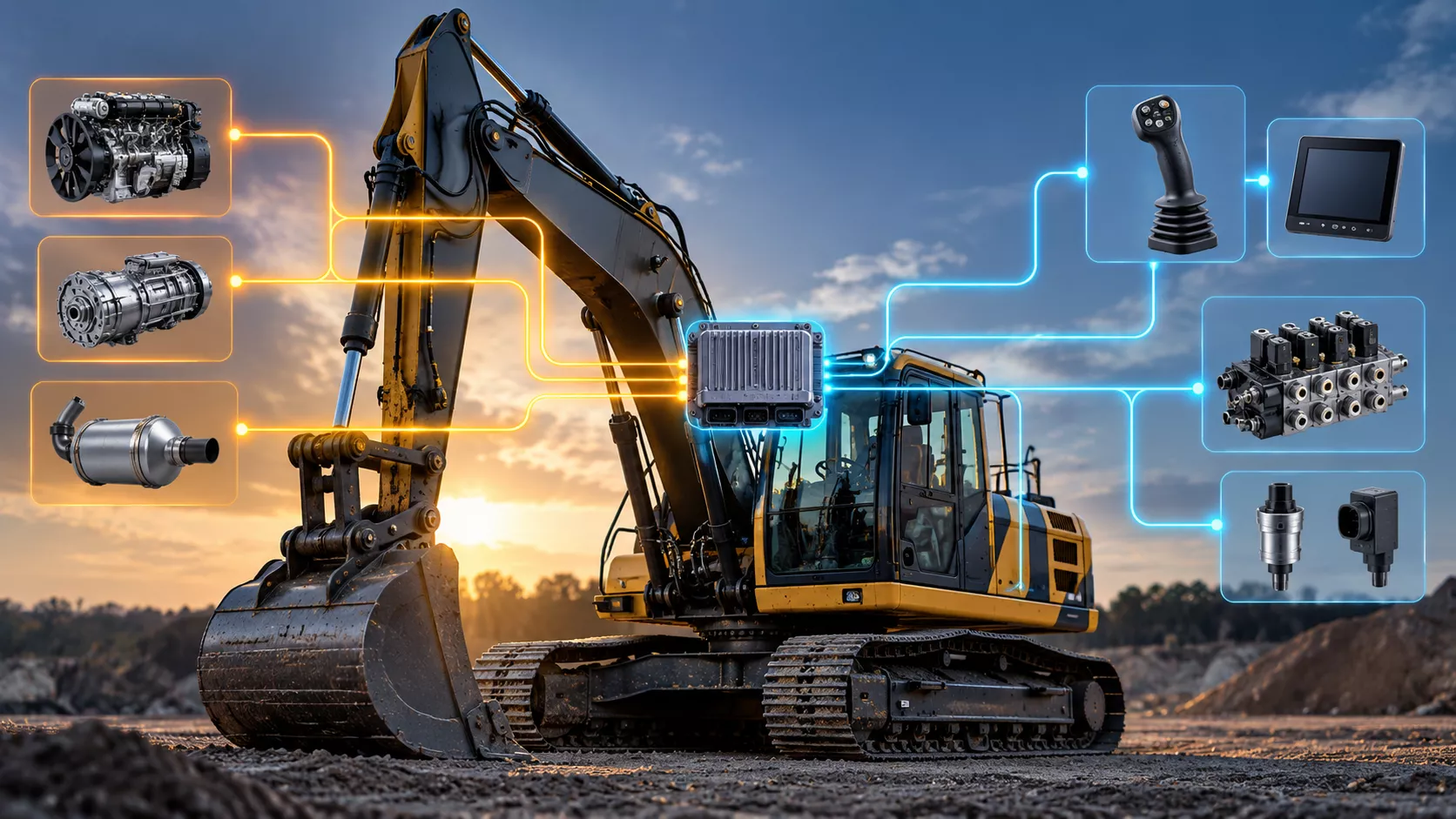
In practice the question is rarely "CANopen or J1939 for the whole machine". Many machines have two or more CAN networks: a J1939 bus for the powertrain and a CANopen bus for the working functions. The machine controller sits on both and acts as a gateway. It reads engine data from J1939, reads the joysticks from CANopen and commands the proportional valves for boom, arm, bucket and swing.
Separating the buses also keeps bus load under control. A joystick that sends its position at a high rate does not compete with engine and aftertreatment messages for bandwidth.
Which protocol for your joystick?
The joystick follows the bus of the controller it talks to. A few practical rules:
- Your controller reads operator inputs on a CANopen bus: choose CANopen. You gain configuration over the bus and, where needed, a route to CANopen Safety.
- Your machine has a single J1939 network or a J1939-based controller: choose J1939. Standard joystick messages keep integration simple.
- You build telehandlers, cranes, aerial work platforms or other lifting equipment: CANopen is the common choice, because load moment control and boom sensing are usually CANopen devices.
- You use two joysticks, as on an excavator: make sure each can have its own node ID or source address, so both can share one bus.
- You retrofit or build a simple machine without a CAN controller: an analog output, if required redundant, can be the most practical solution.
Integration checklist
Whatever the protocol, these points prevent most start-up problems:
- Bit rate: all nodes on one bus must use the same bit rate.
- Address: every node needs a unique node ID (CANopen) or source address (J1939). Two identical joysticks on one bus need different addresses.
- Termination: a CAN bus needs a 120 Ω resistor at each end. Check whether the device has one built in. Many joysticks, including our C25 CAN version, are delivered without it.
- Documentation: ask for the EDS file (CANopen) or the message description (J1939) before you start writing software.
- Safety: decide early which functions are safety-related and how the signal is monitored, for example with redundant sensing in the joystick.
CAN joysticks from Althen Controls
Althen Controls supplies Hall effect joysticks for mobile machinery with either protocol. The C25, H4 and H6 series are available with CANopen output from 10 kbit/s to 1 Mbit/s or with SAE J1939 at 250 kbit/s. The J1939 versions can be ordered with different node addresses, so a left-hand and right-hand joystick can share one bus. For machines without CAN, the same joysticks are available with analog and redundant analog outputs.
Building construction machinery? See how these joysticks are applied in excavators, wheel loaders and telehandlers on our Construction Machinery page.

Talk to our Controls specialists
Not sure which protocol fits your machine architecture? Tell us which controller you use, and we help you select and configure the right joystick.